Fluid-borne noise
A prime source of noise in hydraulic systems is pump flow ripple, which produces fluid-borne noise or pressure ripple, resulting in vibration and air-borne noise.
The Centre is well known for its research in this area, which has led to the development of International Standards for the measurement of flow ripple. We have developed a methodology to measure the noise-related characteristics of a wide range of fluid power components.
We offer the following software packages for commercial use:
FBN for measurement of fluid-borne noise
The fluid-borne noise characteristics of positive displacement hydraulic pumps can be measured using the Secondary Source test method. This forms the basis of British Standard BS6335 pt. 1 and ISO 10767-1: 1996 for the rating of pump fluid-borne noise. Hydraulic motors, valves and hoses can also be tested using this method.
The Secondary Source method is used for determining the flow ripple and impedance of hydraulic components. Flow ripple provides very useful information which would be difficult to achieve by other means. Flow ripple is extremely difficult to measure directly, but is determined indirectly in the Secondary Source method by mathematical analysis of pressure ripple measurements at three points along a pipe. The FBN package performs data acquisition, analysis and plotting for the test method.

FBN user interface
FBN runs on a PC using a high speed data acquisition card. The software offers high productivity; results can be processed and displayed graphically within seconds of initiating a measurement. Part of a typical flow ripple and impedance display is shown here.
The package has been extensively used for testing a wide range of piston, gear, vane, gerotor and plunger pumps, as well as motors, accumulators, hoses and valves. Several pump and system manufacturers regularly use the software in-house. A particularly strong area of application has been the testing of automotive power steering pumps and flexible hoses, which has led to a number of pump and system design improvements.
FBN Features
- High-speed data acquisition with sophisticated order tracking and excellent frequency resolution
- Real-time signal display during data acquisition*
- Programmable, precise motor speed control*
- ISO 10767-1 compatibility settings*
- Calculation of speed of sound to a high accuracy (typically +/-0.5%) by analysis of pressure ripple measurements
- Inbuilt diagnostics for tracing measurement faults
- Inbuilt transducer calibration procedure
- Customisable fluid property database
- Wide range of output options
- High quality, flexible graph plotting
- Mathematical modelling of impedance with automatic fitting to measured data
- Mathematical modelling of hose characteristics*
- New features in version 4.10
New features in version 4.10 include secondary source speed sweep control and real time signal display. Note in the acquisition display above how the flow spikes produced by the secondary source can clearly be seen in the pressure ripple signals, and note the differences in the pressure ripple signals between the three transducers.
Typical FBN Measurements
Here are some typical flow ripple measurements performed on a variety of hydraulic components:
Axial piston pump
The figure below shows some typical measured flow ripple waveforms for an axial piston pump, at 40 bar (red) and 120 bar (blue). The most striking feature is the reverse flow spike which occurs repeatedly when the delivery port starts to open and the fluid in the cylinder is suddenly pressurised. This increases with pressure. Also apparent is a smaller ripple due to the sinusoidal motion of the pistons.
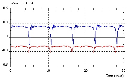
Axial piston pump flow rate waveform at 40 (red) and 120 bar (blue)
This pump contained no relief (silencing) grooves in the portplate and was consequently very noisy. The reverse flow spikes could be reduced by the use of relief grooves. Flow ripple measurements such as the above could be extremely useful in the design of relief grooves; the effect on the reverse flow spikes could be examined in detail.
The corresponding amplitude spectra are shown below. These measurements were taken up to 3.5 kHz and a large number of significant harmonics are apparent.
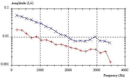
Pump flow rate amplitude spectra at the two previous pressures
Reciprocating plunger pump
The picture below shows some measured flow ripple waveforms for a large reciprocating plunger pump, working with 95:5 water-oil emulsion, as used in mining applications. The red line is for a standard pump, and the blue line for a pump with modified valves. The flow ripple waveform is characteristic of such pumps, and the negative peaks occur when the valves open and close. The modified valves were found to have a faster response, resulting in advanced timing, as can be seen from the waveforms. The flow ripple is slightly smaller for the modified valves, and there was an associated increase in volumetric efficiency and reduction in noise. The measured flow ripple was of great value in determining the valve timing.
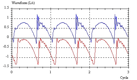
Flow ripple of plunger pump with standard (red) modified (blue) valves
Power steering pump
Here are some typical flow ripple measurements for a power steering vane pump, at low pressure (red) and high pressure (blue). Measurements such as these have proved extremely useful for the design of low noise pumps, and have also been used in the prediction of pressure ripple in power steering systems. Such predictions have been used to assist in the design of low noise systems.
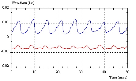
Flow rate waveform of power steering pump at low(red) and high (blue) pressure
The measured source impedance of this pump is shown below. These measurements are of very high quality, and are accurate over a very broad frequency range. A few 'outliers' are apparent in the data, but the software is capable of identifying and rejecting such points. The source impedance is needed before the pump's flow ripple can be determined, and is also needed for prediction of pressure ripple in circuits.
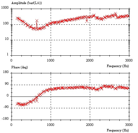 Source impedance of analysed power steering pump
Flexible hose
Hoses can have a very strong effect on fluid-borne noise levels. They generally exhibit very complex fluid-borne noise characteristics, because of wave behaviour in the hose wall as well as in the fluid. For system modelling, accurate flexible hose models are essential. However the dynamic parameters for such models are difficult if not impossible to measure accurately by traditional means.
The fluid-borne noise characteristics of a flexible hose can be described by its impedance matrix, which relates the pressure and flow ripples at both ends. This can be measured using the FBN package. A typical result is shown below. This shows the amplitude spectrum of one term of the impedance matrix. The blue lines are measured data using the FBN package.
A typical result is shown below. This shows the amplitude spectrum of one term of the impedance matrix. The blue lines are measured data using the FBN package. The red lines are modelled characteristics. The model parameters were adjusted to get the best fit with the measurements, and the curve fitting was performed using the FBN package. Good agreement between model and measurements can be seen.
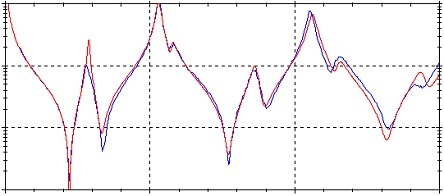
Frequency response of hydraulic hose red=modelled blue=measured
FBN Licensing Options
FBN licenses are available for commercial use. A standalone version and a MATLAB® toolbox version are available. Test rig specifications and designs, and user instruction, can also be provided. Advice, maintenance, support and upgrade packages are available for an annual fee. Please enquire for current prices.
Alternatively, testing and analysis can be performed on a consultancy basis at the University of Bath, where we have a wealth of experience in the test method and interpretation of results.
Prasp Matlab/Simulink toolbox for modelling fluid borne noise
Prasp ('Pressure Ripple Analysis Software Package') is a MATLAB/Simulink® toolbox to model or simulate the fluid borne noise (FBN) characteristics of hydraulic circuits. FBN is pressure and flow pulsations or ripple.
Areas of application include: automotive power-assisted steering, mobile machinery, aerospace, marine, industrial hydraulics. Noise is often a serious problem in any of these applications, and Prasp provides a powerful tool for analysis and design of low-noise systems.
Prasp includes mathematical models for most common hydraulic components. The user can also create new models if necessary. In addition to the mathematical models, components may also be represented using spectral data read from files. These files are compatible with experimental results processed using the FBN package (available from the University of Bath). Circuits can be built up using experimental data, mathematical models or a combination of the two.
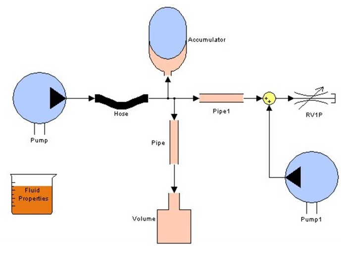
Prasp user interface showing the clear depiction of hydraulic circuits
Prasp circuit models are not solved in the same way as normal Simulink models, but a separate MATLAB solver and graphical post-processor is provided with the Prasp toolbox. Prasp operates in the frequency domain.
Results can be plotted as pressure ripple, flow ripple, impedance or pressure ratio. Transmission loss and transfer matrices can also be calculated. Frequency and parametric sweeps can be performed. For example, this graph shows the transmission loss of an expansion chamber for different diameters and frequencies.
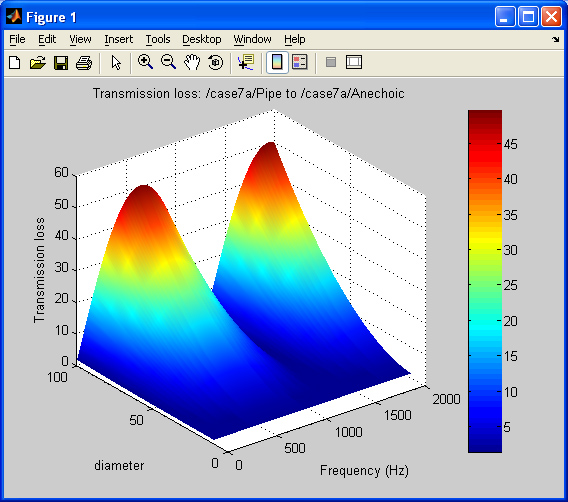
Example output of Prasp
Features
- Clear hydraulic circuit diagrams
- User-defined models
- compatible with measured component data
- parametric sweeps for system optimisation
- advanced models for flexible hoses, including 'tuner' insert.
Prasp Licensing Options
Please enquire about availability and price of Prasp licenses for commercial use.
Alternatively, analysis can be performed on a consultancy basis at the University of Bath, where we have a wealth of experience in the measurement and modelling of fluid-borne noise and interpretation of results.
Fluid circuit simulation
In the past, the Centre has also offered the interactive dynamic simulation package Bathfp. This software is not offered for sale anymore. Instead we use and recommend the commercial package Siemens Simcenter Amesim instead, which grew out of the development work for Bathfp.
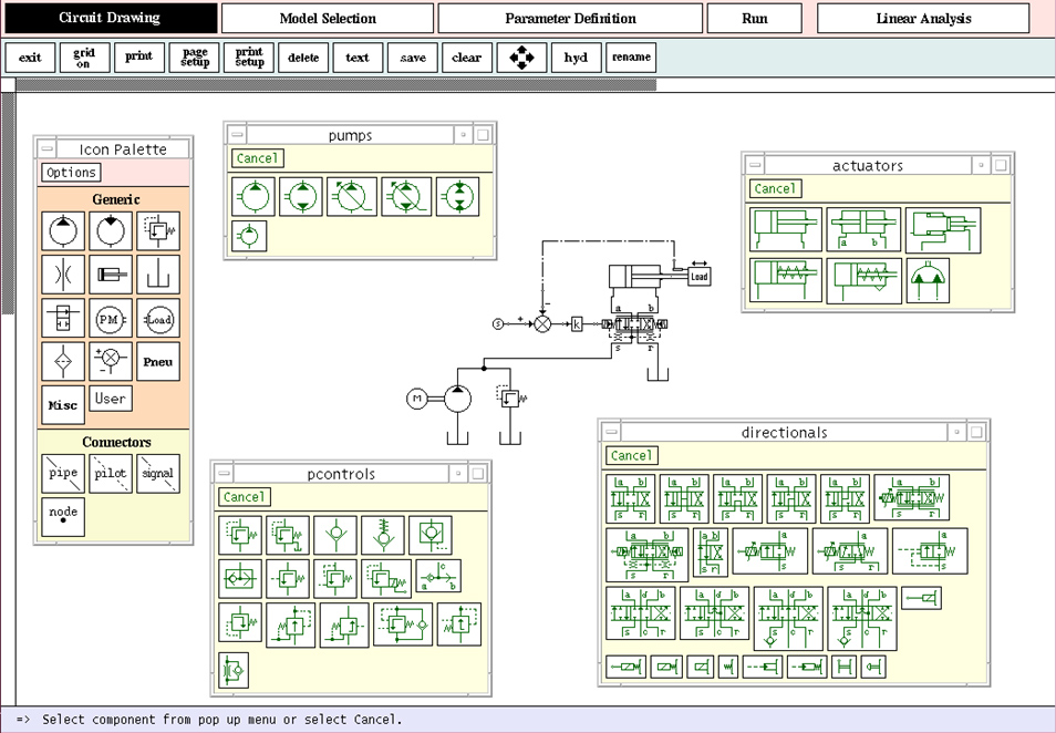
Bathfp simulation software user interface
Dynamic simulation of multi-physics systems
Our expertise in the dynamic simulation of multi-physics systems has resulted in the development of a software package, DYSIM.
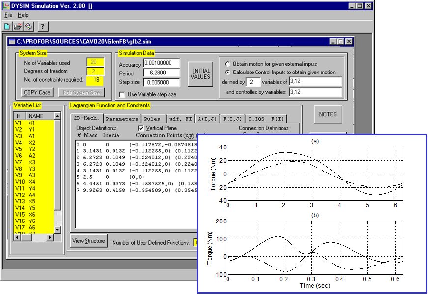
User interface and example output of DYSIM
We have used this in-house for inverse dynamic modelling of multi-body systems for the synthesis of mechanisms, as well as for real-time control of complex mechanical systems.